INDUSTRY: Mining, Aggregate, Recycle
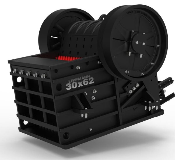
Bare Jaw Crusher
Bare Jaw
Our world-renowned jaws lie at the core of Lippmann’s product offering and have been manufactured in Milwaukee, WI, since 1923. Fabricated with extra heavy ribbed steel plate construction, Lippmann jaw crushers have proven time and again they provide maximum strength, durability, and reliability at the lowest cost of ownership in the industry.
Frames are stress-relieved before machining to ensure uniform heavy-duty strength and trouble-free operation on a stout, easy-to-move truck frame. Jaw crushers also feature an oversized shaft, tapered roller bearings, reversible jaw dies, and an oil-bath lubrication system.
Highlights

Heavy-duty, oversized heat-treated shafts forged of special alloy to handle overloads and hard material
Radial thrust tapered roller bearings–the best design for absorbing and withstanding shock, radial, and thrust loads
Longer jaw length to provide increased crushing area, steeper nip angle and increased capacity
Curved jaw dies to provide non-choking crushing action, reversible for increased wear
Rugged frame with heavy-ribbed steel plate construction at stress points, stress relieved by heat treating before machining
Protected pitman hub with rock rib
Dynamically balanced flywheels reduce vibration
Toggle plate is set at an optimum angle for maximum crushing
Positive setting adjustment shims provide easy change of discharge opening with aid of hydraulic pumps
Lubrication easily checked; positive oil-level gauges assure correct lubrication of bearings
Inside contact surfaces are fully machined
Standard Features
- Heavy-duty, oversized heat treated shafts forged of special alloy to handle overloads and hard material
- Radial thrust tapered roller bearings–the best design for absorbing and withstanding shock, radial, and thrust loads
- Longer jaw length to provide increased crushing area, steeper nip angle and increased capacity
- Curved jaw dies to provide non-choking crushing action, reversible for increased wear
- Rugged frame with heavy-ribbed steel plate construction at stress points, stress relieved by heat treating before machining
- Inside contact surfaces are fully machined
- Lubrication easily checked positive oil-level gauges assure correct lubrication of bearings
- Protected pitman hub with rock rib
- Cheek plates are one-piece or two-piece for easy replacement
- Positive setting adjustment shims provide easy change of discharge opening with aid of hydraulic pumps
- Extension wedges hold jaw dies rigidly across full width
- Dynamically balanced flywheels reduce vibration
- Toggle plate is set at an optimum angle for maximum crushing
Technical Specs
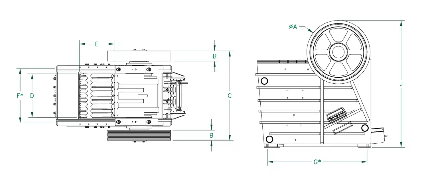
*See diagram below for letter reference.
| A | B | C | D | E | F* | G* | H¹ | J | Mounting Bolt Diameter | Crusher Weight | |
|---|---|---|---|---|---|---|---|---|---|---|---|
| Inches | Inches mm | Inches mm | Inches mm | Inches mm | Inches mm | Inches mm | Inches mm | Inches mm | Inches mm | Inches mm | LBS KG |
| 30×48 | 60 1524 | 16 413 | 98 2489 | 48 1219 | 30 762 | 61 1549 | 84 2134 | 70 1778 | 105 2667 | 2 52 | 64,200 29,121 |
| 30×55 | 54 1372 | 14 356 | 97 2451 | 55 1397 | 30 762 | 72 1829 | 83 2108 | 37 949 | 108 2731 | 2 39 | 57,500 26,082 |
| 30×62 | 60 1524 | 16 413 | 110 2794 | 62 1575 | 30 762 | 73 1854 | 92 2337 | 64 1613 | 99 2508 | 2 52 | 73,000 33,112 |
| 34×47 | 60 1500 | 15 380 | 94 2380 | 47 1194 | 34 864 | 76 1928 | 95 2400 | 73 1850 | 107 2700 | 11/16 18 | 61,710 27,990 |
| 36×50 | 60 1524 | 16 413 | 102 2578 | 50 1270 | 36 914 | 63 1600 | 103 1219 | 82 2083 | 119 3023 | 2 52 | 92,000 41,730 |
| 38×62 | 68 1727 | 21 533 | 122 3092 | 62 1575 | 38 965 | 73 1854 | 103 2616 | 82 2083 | 124 3137 | 2 52 | 117,250 53,184 |
| 39×51 | 63 1600 | 18 448 | 105 2644 | 51 1296 | 39 991 | 78 1980 | 109 2765 | 88 2220 | 131 3320 | 1 25 | 88,516 40,150 |
| 42×48 | 68 1727 | 21 533 | 111 2826 | 48 1219 | 42 1067 | 61 1549 | 114 2896 | 106 2680 | 148 3747 | 2 52 | 130,000 58,967 |
| 50×62 | 87 2210 | 14 356 | 123 3124 | 62 1575 | 50 1270 | 77 1956 | 137 3470 | 119 3032 | 174 4423 | 3 64 | 218,000 98,883 |
*Dimension denotes crusher mounting hole centers.
1 Dimension is from bottom of mounting surface to top of feed side of crusher frame (Jaw can be mounted flat or tipped, drawing to confirm orientation is recommended).
| GAPE X WIDTH Inches mm | HP (Electric Drive Motor) | RPM | HYDRAULIC TOGGLE OR MANUAL TOGGLE PLATE OPTION | MANUAL TOGGLE PLATE OPTION ONLY | ||||||||||||||
|---|---|---|---|---|---|---|---|---|---|---|---|---|---|---|---|---|---|---|
| CLOSED SIDE SETTING (CSS) INCHES | ||||||||||||||||||
| Inches mm | 3 77 | 3.5 89 | 4 102 | 4.5 115 | 5 127 | 6 153 | 7 178 | 8 204 | 10 254 | 12 305 | 14 356 | |||||||
| 30×48 770×1220 | 200 | 230 | STPH MTPH | 226-259 205-235 | 259-303 235-275 | 303-378 275-343 | 339-417 308-378 | 378-454 343-412 | 455-531 413-482 | 594-659 539-598 | 659-755 598-685 | |||||||
| 30×55 770×1400 | 200 | 230 | STPH MTPH | 250-300 227-272 | 288-345 261-313 | 345-415 313-377 | 400-480 363-435 | 420-500 381-454 | 500-600 454-544 | 600-715 544-650 | 720-860 653-780 | |||||||
| 30×62 770×1580 | 200 | 220 | STPH MTPH | 220-243 200-220 | 280-309 254-280 | 337-375 306-340 | 399-421 362-382 | 420-463 381-420 | 491-541 445-491 | 570-628 517-570 | 650-717 590-650 | 799-882 725-800 | ||||||
| 36×50 920×1270 | 250 | 220 | STPH MTPH | 342-375 310-340 | 375-468 340-425 | 421-527 382-478 | 468-573 425-520 | 573-661 520-600 | 661-750 600-680 | 750-926 680-840 | 927-1136 841-1031 | 1135-1246 1030-1130 | 1177-1316 1068-1194 | |||||
| 38×62 970×1580 | 250 300 | 210 | STPH MTPH | 372-424 337-385 | 408-468 370-425 | 459-527 416-478 | 510-586 463-532 | 624-713 566-647 | 720-823 653-747 | 816-936 740-849 | 1008-1149 914-1042 | 1236-1397 1121-1267 | 1356-1559 1230-1414 | |||||
| 42×48 1070×1220 | 250 | 210 | STPH MTPH | 386-489 350-444 | 441-550 400-499 | 489-595 444-540 | 599-689 543-625 | 688-780 624-708 | 788-966 715-876 | 966-1177 876-1068 | 1069-1178 970-1069 | 1176-1309 1067-1188 | ||||||
| 50×62 1270×1580 | 300 350 | 190 | STPH MTPH | 600-650 544-590 | 700-775 635-703 | 850-915 771-830 | 980-1088 889-987 | 1199-1301 1088-1180 | 1400-1499 1270-1360 | 1599-1700 1451-1542 | ||||||||
Lippmann reserves the right to make changes to the information and design of the machines on this website without reservation and notification to the users. Information at time of publication is considered accurate – Lippmann assumes no liability resulting from errors or omissions in this document.
